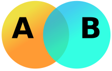
Venn diagram
A Venn diagram (also called primary diagram, set diagram or logic diagram) is a diagram that shows all possible logical relations between a finite collection of different sets. These diagrams depict elements as points in the plane, and sets as regions inside closed curves. A Venn diagram consists of multiple overlapping closed curves, usually circles, each representing a set. The points inside a curve labelled S represent elements of the set S, while points outside the boundary represent elements not in the set S. This lends to easily read visualizations; for example, the set of all elements that are members of both sets S and T, S ∩ T, is represented visually by the area of overlap of the regions S and T. In Venn diagrams the curves are overlapped in every possible way, showing all possible relations between the sets. They are thus a special case of Euler diagrams, which do not necessarily show all relations. Venn diagrams were conceived around 1880 by John Venn. They are used to teach elementary set theory, as well as illustrate simple set relationships in probability, logic, statistics, linguistics, and computer science.
A Venn diagram in which the area of each shape is proportional to the number of elements it contains is called an area-proportional or scaled Venn diagram.
History

Stained-glass window with Venn diagram in Gonville and Caius College, Cambridge
Venn diagrams were introduced in 1880 by John Venn in a paper entitled On the Diagrammatic and Mechanical Representation of Propositions and Reasonings in the "Philosophical Magazine and Journal of Science", about the different ways to represent propositions by diagrams. The use of these types of diagrams in formal logic, according to Frank Ruskey and Mark Weston, is "not an easy history to trace, but it is certain that the diagrams that are popularly associated with Venn, in fact, originated much earlier. They are rightly associated with Venn, however, because he comprehensively surveyed and formalized their usage, and was the first to generalize them".
Venn himself did not use the term "Venn diagram" and referred to his invention as "Eulerian Circles".For example, in the opening sentence of his 1880 article Venn writes, "Schemes of diagrammatic representation have been so familiarly introduced into logical treatises during the last century or so, that many readers, even those who have made no professional study of logic, may be supposed to be acquainted with the general nature and object of such devices. Of these schemes one only, viz. that commonly called 'Eulerian circles,' has met with any general acceptance..." Lewis Carroll (Charles Dodgson) includes "Venn's Method of Diagrams" as well as "Euler's Method of Diagrams" in an "Appendix, Addressed to Teachers" of his book "Symbolic Logic" (4th edition published in 1896). The term "Venn diagram" was later used by Clarence Irving Lewis in 1918, in his book "A Survey of Symbolic Logic".
Venn diagrams are very similar to Euler diagrams, which were invented by Leonhard Euler in the 18th century.[note 1][6][7] M. E. Baron has noted that Leibniz (1646–1716) in the 17th century produced similar diagrams before Euler, but much of it was unpublished. She also observes even earlier Euler-like diagrams by Ramon Llull in the 13th Century.
In the 20th century, Venn diagrams were further developed. D. W. Henderson showed in 1963 that the existence of an n-Venn diagram with n-fold rotational symmetry implied that n was a prime number.[10] He also showed that such symmetric Venn diagrams exist when n is five or seven. In 2002 Peter Hamburger found symmetric Venn diagrams for n = 11 and in 2003, Griggs, Killian, and Savage showed that symmetric Venn diagrams exist for all other primes. Thus rotationally symmetric Venn diagrams exist if and only if n is a prime number.
Venn diagrams and Euler diagrams were incorporated as part of instruction in set theory as part of the new math movement in the 1960s. Since then, they have also been adopted in the curriculum of other fields such as reading.
Example
This example involves two sets, A and B, represented here as coloured circles. The orange circle, set A, represents all living creatures that are two-legged. The blue circle, set B, represents the living creatures that can fly. Each separate type of creature can be imagined as a point somewhere in the diagram. Living creatures that both can fly and have two legs—for example, parrots—are then in both sets, so they correspond to points in the region where the blue and orange circles overlap. It is important to note that this overlapping region would only contain those elements (in this example creatures) that are members of both set A (two-legged creatures) and are also members of set B (flying creatures.)
Humans and penguins are bipedal, and so are then in the orange circle, but since they cannot fly they appear in the left part of the orange circle, where it does not overlap with the blue circle. Mosquitoes have six legs, and fly, so the point for mosquitoes is in the part of the blue circle that does not overlap with the orange one. Creatures that are not two-legged and cannot fly (for example, whales and spiders) would all be represented by points outside both circles.
The combined region of sets A and B is called the union of A and B, denoted by A ∪ B. The union in this case contains all living creatures that are either two-legged or that can fly (or both).
The region in both A and B, where the two sets overlap, is called the intersection of A and B, denoted by A ∩ B. For example, the intersection of the two sets is not empty, because there are points that represent creatures that are in both the orange and blue circles.


No comments:
Post a Comment